In our previous deep dive into the Structure of PEMFC, we explored how a single fuel cell works. However, there is a harsh reality: A single cell only generates a voltage of about 0.7V - 0.8V.
This isn’t even enough to light up a small LED bulb, let alone power a car that requires 300V - 600V and hundreds of kilowatts (kW) of power.
So, how do we solve this problem? We don’t make the cell 100 times bigger; instead, we connect hundreds of cells together. This assembly is called a Fuel Cell Stack. But a stack alone cannot function—it needs a complex life-support system known as the Balance of Plant (BoP).
In this article, we will explore the Fuel Cell Stack and the BoP system that brings it to life. 🛠️
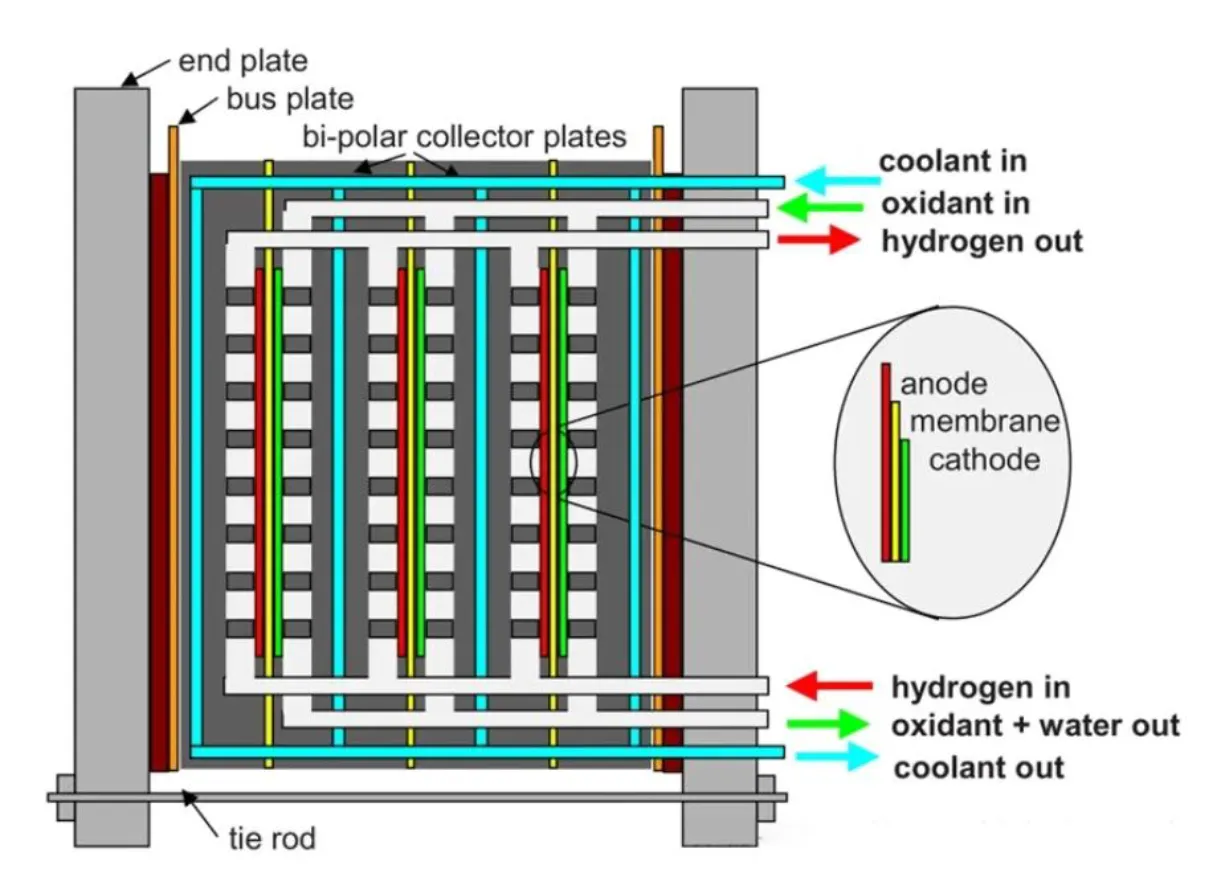
1. The Fuel Cell Stack: Strength in Numbers
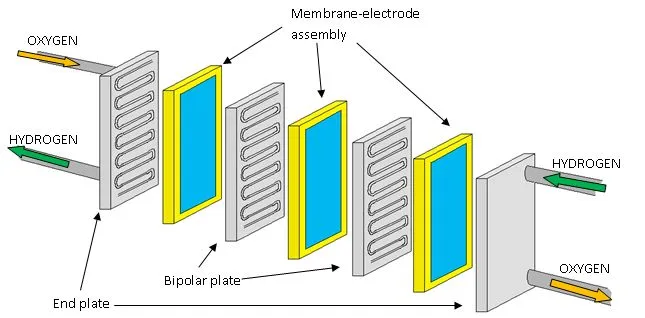
The concept of a “Stack” is simple: It involves stacking multiple fuel cells in series.
The Principle of Accumulation
According to Kirchhoff’s laws, when connected in series, voltage accumulates:
Where:
- : Total voltage of the stack.
- : Number of cells (typically 300 - 400 cells for a passenger car).
- : Average voltage of a single cell.
For example, to achieve 400V, we need to stack approximately 500-600 cells together.
The Challenges of Stacking
It sounds simple—just “stack them up”—but technically, a Stack is an incredibly sensitive component:
- Uniformity Issue: Hydrogen and Oxygen must be distributed evenly to all 400+ cells. If cell #1 gets enough gas but cell #400 (farther down the line) is starved due to pressure drop, that cell will suffer from Starvation, causing voltage drops, heat generation, and potentially damaging the entire Stack.
- The “Weakest Link” Effect: Since the current passing through all cells is the same (), if just one cell fails, the performance of the entire system is dragged down by that single weak point.
Control Perspective: This is why a Cell Voltage Monitoring (CVM) system is critical. It must continuously monitor the voltage of every single cell to detect anomalies early.
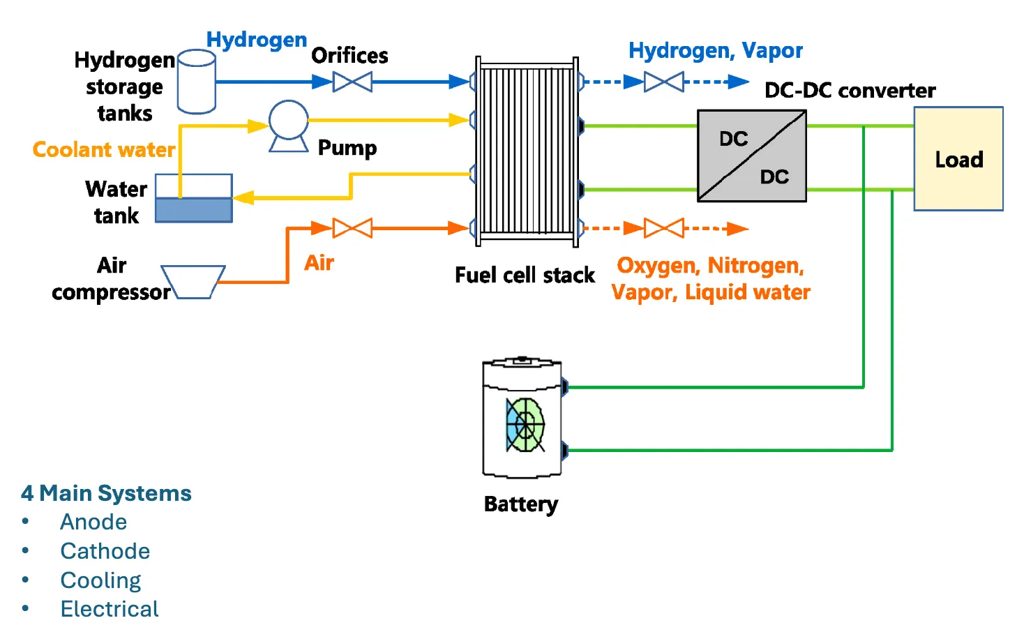
2. Balance of Plant (BoP): The Life-Support System
A Fuel Cell Stack sitting alone is just a block of metal and polymer. It cannot function on its own. Think of it like a human heart: to beat, it needs lungs to breathe, blood vessels for nourishment, and sweat glands for cooling.
All the auxiliary components that help the Stack function are collectively called the Balance of Plant (BoP). In simulation and optimization problems, the BoP represents the Parasitic Load—the energy consumers that we must minimize.
We can divide the BoP into four main sub-systems:
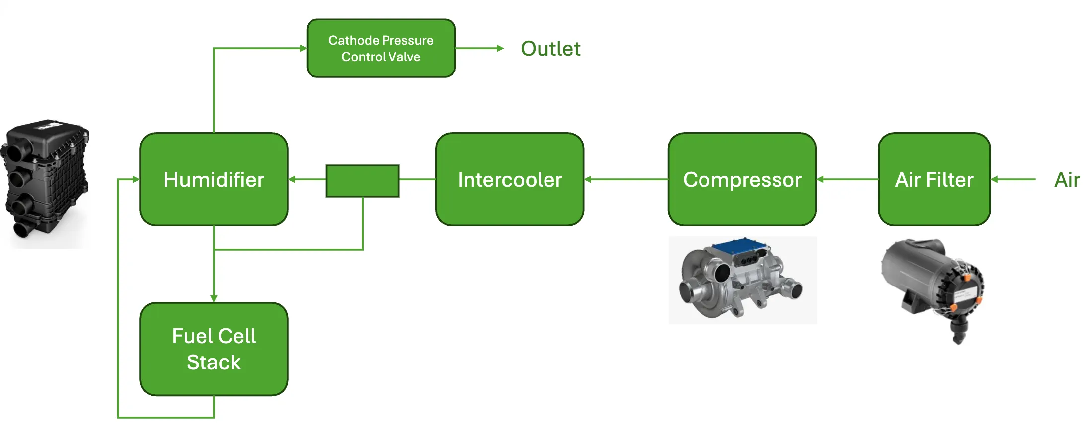
a. Air Supply System (The Lungs)
This is arguably the most critical and energy-demanding sub-system.
- Main Component: Air Compressor.
- Mission: To pump Oxygen from the ambient air into the Cathode at precise pressure and flow rates.
- Control Challenge: The compressor consumes a significant amount of electricity (up to 10-15% of the stack’s output).
- Pump too hard? You waste energy and lower system efficiency.
- Pump too weak? The stack suffers Oxygen Starvation, permanently damaging the catalyst.
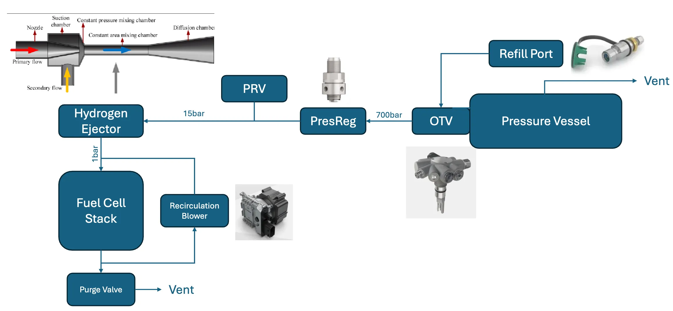
b. Fuel Supply System (The Stomach)
- Main Components: High-pressure Hydrogen Tank, Pressure Regulator Valve, Recirculation Pump.
- Mechanism: Hydrogen from the tank (stored at 700 bar) is pressure-regulated and injected into the Anode. Crucially, any unreacted Hydrogen is not wasted; it is recirculated back to the inlet to be used again.
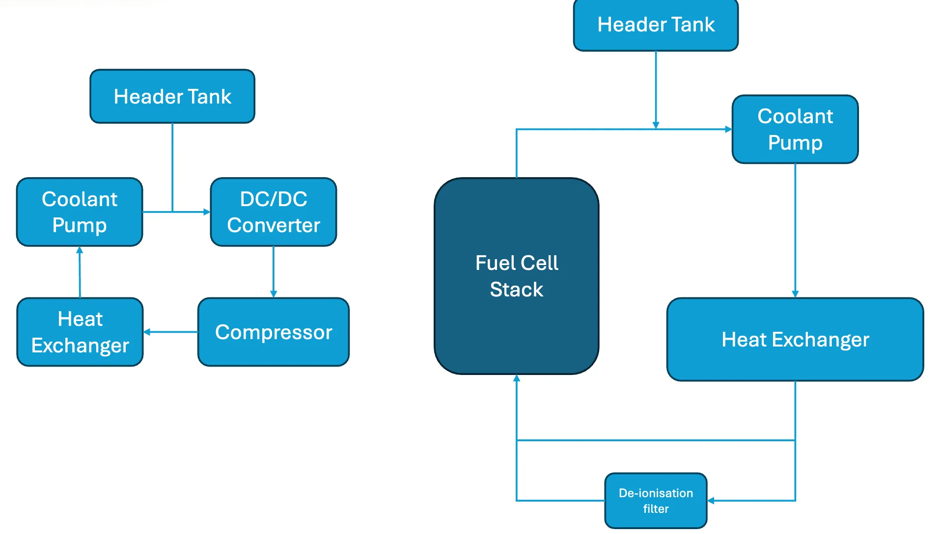
c. Thermal & Water Management (The Sweat & Hydration)
PEMFCs operate best within a strict temperature window of 60°C - 80°C.
- Main Components: Coolant Pump, Radiator, Fan.
- Mission: The electrochemical reaction generates a lot of heat. Without cooling, the polymer membrane would melt. Conversely, if it’s too cold, the reaction efficiency drops.
Furthermore, the PEM membrane needs to stay hydrated (like human skin):
- Too dry: Proton conductivity drops, resistance increases -> Voltage loss.
- Too wet (Flooding): Water blocks the porous layers, preventing gas from reaching the catalyst -> The cell “drowns.”
- Solution: We use Humidifiers to balance the humidity of the incoming gas streams.
d. Electrical Management System
3. Why Do We Need a Control Strategy?
By now, you can see the complexity surfacing. We are not just controlling a battery; we are conducting a symphony of compressors, valves, pumps, and fans.
The ultimate goal of any control strategy is to optimize the Net Power:
Where:
- : Power generated by the stack (the higher, the better).
- : Power consumed by BoP auxiliary devices (the lower, the better).
The Trade-off: To increase , we need to pump more air at higher pressure (increasing oxygen flow). But doing so forces the compressor to work harder, causing to skyrocket. The result? might actually decrease!
The Control Mission: To find the Optimal Operating Point for every situation, ensuring the system is durable, stable, and achieves maximum efficiency.
Conclusion
From a tiny single cell, by connecting hundreds of them into a Fuel Cell Stack and supporting them with a complex Balance of Plant (BoP), we have created a complete, functioning Fuel Cell Engine.
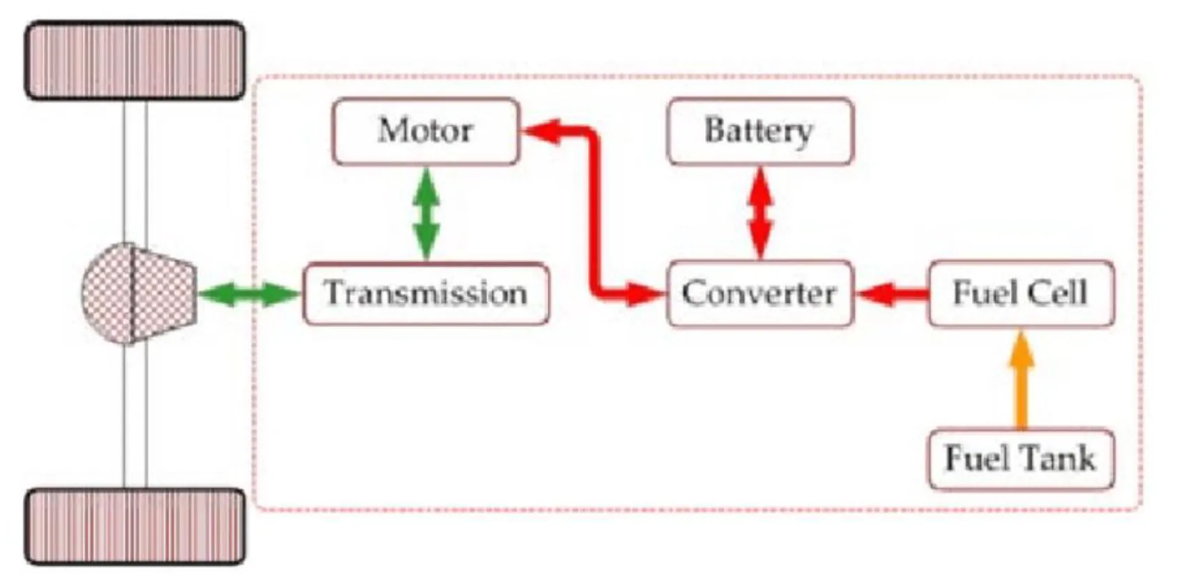
However, Fuel Cells have a fatal weakness: They are slow to react. Due to mechanical constraints (compressor spin-up time) and chemical reaction dynamics, when you stomp on the pedal to overtake, the system lags. The car would feel sluggish.
To solve this, we need a companion that reacts instantly: A Battery or a Supercapacitor. This combination creates a Fuel Cell Hybrid Powertrain.
That is the fascinating topic we will discuss in the next post! See you then. 👋