In the previous post Overview of Fuel Cell Technology, we knew that a Fuel Cell is a device that converts Hydrogen into electricity. But what exactly is the “magic” happening inside that box?
Why does Hydrogen gas simply go in one end, and electricity comes out the other?
Since there are many types of fuel cells, in this article, we will “dissect” the most popular type used in the transportation industry:
PEMFC - Proton Exchange Membrane Fuel Cell.
This is also the main subject of research I am currently pursuing.
Consider this article as fundamental knowledge to understand so that we can apply in simulating later! 🚀
1. Structure of PEMFC: A Multi-Layered Sandwich
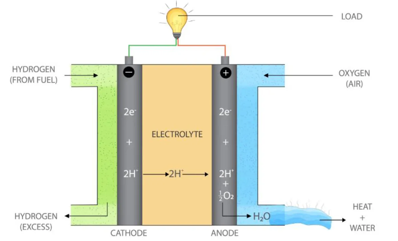
As shown in the figure above, if you cut through a single fuel cell, its structure looks exactly like a multi-layered sandwich. Let’s imagine going from the outside in:
The Pastry: Bipolar Plates
These are the two hard outer shells (depicted in the image as gray borders), usually made of graphite or metal.
- Functions:
- Gas Distribution: The surface features small grooves (Flow channels) to distribute Hydrogen and Oxygen evenly across the cell.
- Current Collection: Conducts electrons to the external circuit to power the motor.
- Heat Removal: Helps dissipate the heat generated during the reaction.
The Filling: MEA (Membrane Electrode Assembly)
This is the membrane separating the Positive (Cathode) and Negative (Anode) electrodes, and simultaneously the “heart” of the fuel cell where energy is generated. The MEA actually consists of three thin layers pressed tightly together:
-
Gas Diffusion Layer (GDL):
- Made of porous carbon fiber paper or cloth.
- Helps distribute gas evenly from the flow channels to the catalyst. Crucially, it also helps manage water removal to prevent the cell from “flooding.”
-
Catalyst Layer (CL):
- The most expensive layer, typically containing Platinum (Pt) powder.
- Function: Stimulates the chemical reaction to occur faster. Without it, Hydrogen and Oxygen would just sit there, and no current would be generated.
-
Proton Exchange Membrane (PEM):
- A special polymer membrane located right in the center (commonly Nafion material).
- Special Characteristic: It is an extremely “picky guard.” It ONLY allows Protons () to pass through and absolutely BLOCKS Electrons () and Hydrogen/Oxygen gases.
Note: The “Electron-blocking” property of the PEM is the key to generating electricity. Since electrons cannot take the shortcut through the membrane, they are forced to take the long route through the external wire -> creating an electricity! ⚡
2. Working Principle: The Separation of Hydrogen
The process of generating electricity in a PEMFC is essentially a reverse electrochemical oxidation reaction. Specifically:
At the Anode (Negative Electrode) - Where Hydrogen Enters
Hydrogen gas () is pumped in and diffuses through the GDL to meet the Platinum catalyst layer. Here, the “separation” process occurs:
The Hydrogen molecule splits into two parts:
- Protons with a positive charge ().
- Electrons with a negative charge ().
Separate Journeys
This is where the PEM membrane plays its role:
- The Protons (): Are allowed to tunnel through the PEM membrane to the other side (Cathode).
- The Electrons (): Are blocked. They have no choice but to travel through the bipolar plate, out to the external wire to reach the Cathode. This flow of electrons is the Electric Current that powers the load (vehicle motor, lights, devices…).
At the Cathode (Positive Electrode) - Where Oxygen Enters
On the other side, Oxygen () from the air is blown in. At the cathode catalyst layer, a “reunion” takes place:
- Electrons () return after completing their circuit through the motor.
- Protons () arrive after passing through the membrane.
- Oxygen () is waiting.
These three components combine to form Water () and release heat.
Overall Reaction
Combining both processes, we get the simple equation mentioned in the previous post:
3. V-I Characteristic (Polarization Curve)
In terms of simulation and control, understanding the device’s properties is extremely important. Therefore, PEMFCs also have their own characteristics that we need to grasp. One of the most significant characteristics is the V-I Characteristic Curve (Voltage-Current Characteristic Curve), also known as the Polarization Curve.
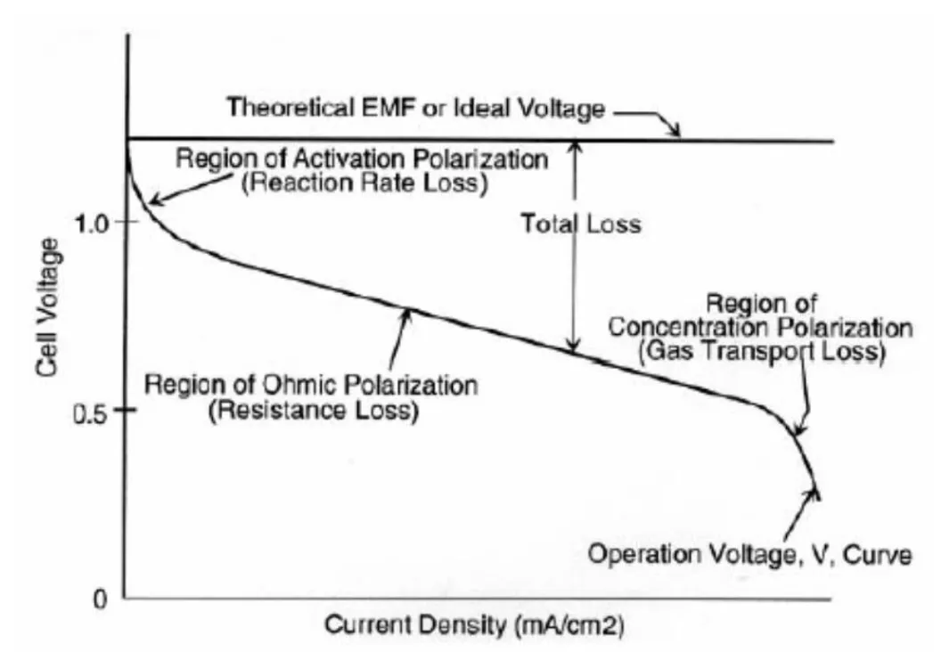
Theoretically, a single fuel cell can generate a voltage of about 0.7-1.2V. However, in reality, when we draw current for use, this voltage drops (Voltage Drop) due to internal losses within the cell.
As shown in Figure 2, the graph showing the relationship between Voltage (V) and Current Density (i) is called the Polarization Curve. It is divided into three main regions of loss:
-
Activation Losses:
- Occurs at low current (start of the graph).
- Cause: Energy is required to “kick-start” the chemical reactions on the catalyst surface.
- Effect: Voltage drops rapidly from 1.23V to about 0.9V as soon as current starts flowing.
-
Ohmic Losses:
- Occurs in the main operating range (middle section, linear).
- Cause: Resistance of the PEM membrane (impeding protons) and resistance of the electrode plates (impeding electrons).
- Effect: Voltage decreases linearly according to Ohm’s Law (). This is the zone where we typically want the fuel cell to operate.
-
Concentration Losses:
- Occurs at very high current (end of the graph).
- Cause: Gases (Hydrogen/Oxygen) cannot be supplied fast enough to the reaction surface, or water produced blocks the pores (flooding) of the catalyst membrane.
- Effect: Voltage plummets drastically.
Because of these characteristics, during the simulation and design of control systems for PEMFCs, we need to ensure the cell operates primarily in the Ohmic Losses region to optimize efficiency and protect the lifespan of the fuel cell.
Therefore, developing suitable Control Strategies to maintain stable operation in this region is absolutely essential.
I will share more details on the mentioned topic in upcoming posts! 😉
Conclusion
In summary, a PEMFC is not an “energy storage tank” like other electric batteries such as Lithium-ion, but rather a “power generation plant.” Hydrogen and Oxygen fuel are continuously supplied, and it will continuously generate electricity thanks to its special structure and the selective nature of the PEM.
However, a single cell generating only about 0.7V-1.2V is too small to operate a vehicle. In the next post, the Balance of Plant (BoP) systems will be discussed to help operate a complete and optimal fuel cell system.
See you in the next post! 👋